CU Boulder Projects
ECEN 5517: Power Electronics and Photovoltaic Power Systems Laboratory
Photovoltaic Conversion System
In this class, groups are tasked with building and validating three converters consisting of an MPPT buck converter, cascaded boost converter, and modified sine-wave inverter. A standalone PV panel cart was provided for each group, which acts as the buck input. The buck converter found the maximum power point and charges the lead-acid battery. The battery voltage (ranging from 11.75 V for 25% SoC to 12.80 V for 100% SoC) is then stepped up to 150 V by the double or cascaded boost, and then inverted into 120 Vrms, 60 Hz to power a 25 W light bulb load.
MPPT Buck Converter
Designed and debugged the sensing and control hardware for a buck converter used for solar battery charging. The system includes voltage/current sensing, ADC sampling, and a hill-climb MPPT algorithm implemented on a C2000 microcontroller.
- Validated current and voltage sensing across multiple duty-cycle points.
- Fixed a current-sense issue caused by an incorrect common-mode voltage condition.
- Implemented MPPT duty control with filtering, protection limits, and settle timing.
- Demonstrated improved panel power extraction compared with direct energy transfer.
Cascaded Boost Converter
Measured and stabilized a high-voltage cascaded boost converter using experimental frequency-response data. The work focused on connecting measured behavior to controller design rather than relying only on ideal simulation.
- Measured control-to-output and loop-gain responses using a Bode 100 analyzer.
- Fit experimental poles and zeros from damped hardware measurements.
- Built an analog feedback PID compensator for closed-loop voltage regulation.
- Regulated the output above 150 V, meeting all phase margin and load regulation specifications for the assignment.
Modified Sine-Wave Inverter
Built the DC-AC inverter stage and configured the control signals needed to generate both modified sine-wave and filtered sine-wave outputs.
- Soldered the inverter power stage and gate-drive circuitry on perfboard.
- Generated complementary PWM control signals using C2000 code.
- Designed and wound filter inductors for the true sine-wave configuration.
- Produced a 120 Vrms, 60 Hz AC output from the high-voltage boost input.
The following images have been selected to highlight some of the more interesting hardware work that was done to validate the operation and stability of the converters. Since this is a university class, component values and images were chosen to align with academic integrity policies for future years. I would like to express gratitude to Manish Tathode for being an amazing lab partner.
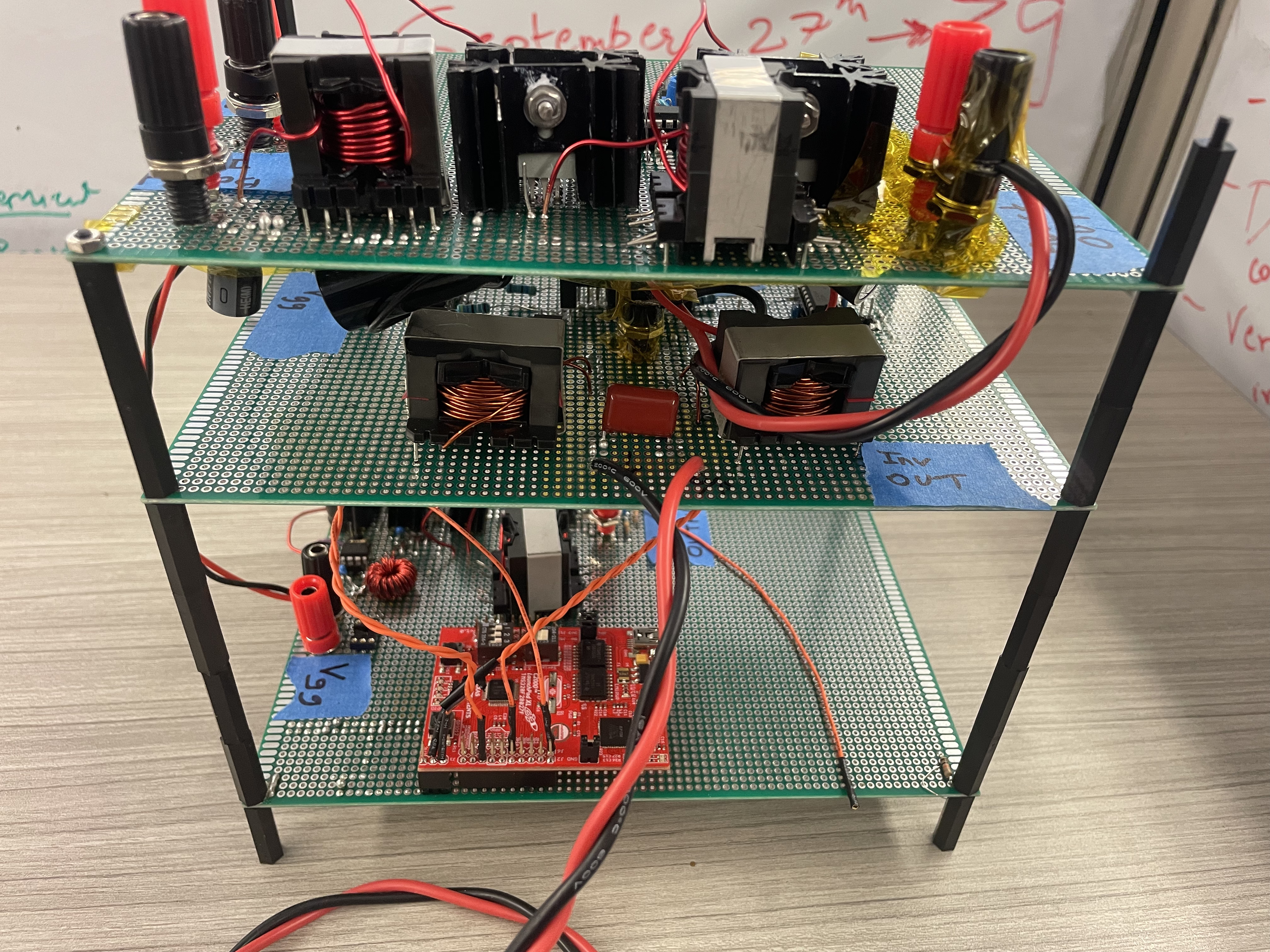
Full converter system: MPPT buck converter, cascaded boost stage, and modified sine-wave inverter. The buck is the bottom protoboard, which houses the C2000 microcontroller, and takes in a 12V signal input. The middle board is the inverter. For the power stage soldering, the gate driver given to the group in the lab kit is designed to drive a half-bridge with a floating channel for bootstrap operation and its pin-out can be found in the IR21904 datasheet. As always, the power stage transistors and capacitor loops, and the gate drive loops were all optimized to be very small. We later soldered in wire loops for the current measurements, and de-soldered them after. Continuity checks were done to ensure that connections were sound and no short-circuits exist between the input source, Vg and the power/signal grounds. The top protoboard is the cascaded boost, which takes in the 12V battery voltage and boosts it up to 150V. And yes, all inductors are hand-wound.
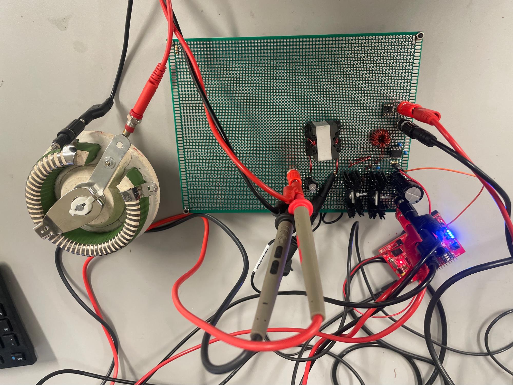
This image depicts the initial functionality testing for the buck converter. First, the PWM output of the Texas Instruments C2000 Piccolo TMS320F28027 microcontroller was set to a duty of 1130/1500, with a duty ratio based on the MPP. Some unit testing was completed at the gate driver portion to ensure that the PWM signals were outputting properly from the microcontroller with an fs = 40 kHz, and that the toroid primary and secondary windings were getting the correct voltages. Then, multimeters were set-up to measure the input and output voltages, and specific voltage and current probes were placed to measure the diode voltage, transistor current, diode current, inductor current, input capacitor current, and the input capacitor voltage. The power stage input was set to around 17.2V or until the output voltage reached 13.0V. These two voltages are based on the solar panel MPP and maximum battery voltage. The load resistor (rheostat) was calculated to be 1.98Ω, and set to 2Ω based on a required 85W output. Due to losses, the actual duty was increased to 1170/1500. The efficiency was calculated to be 94.5%, which is slightly lower than expected. But with conduction losses and the current measurement loops, which create parasitics and ringing, this was to be expected.
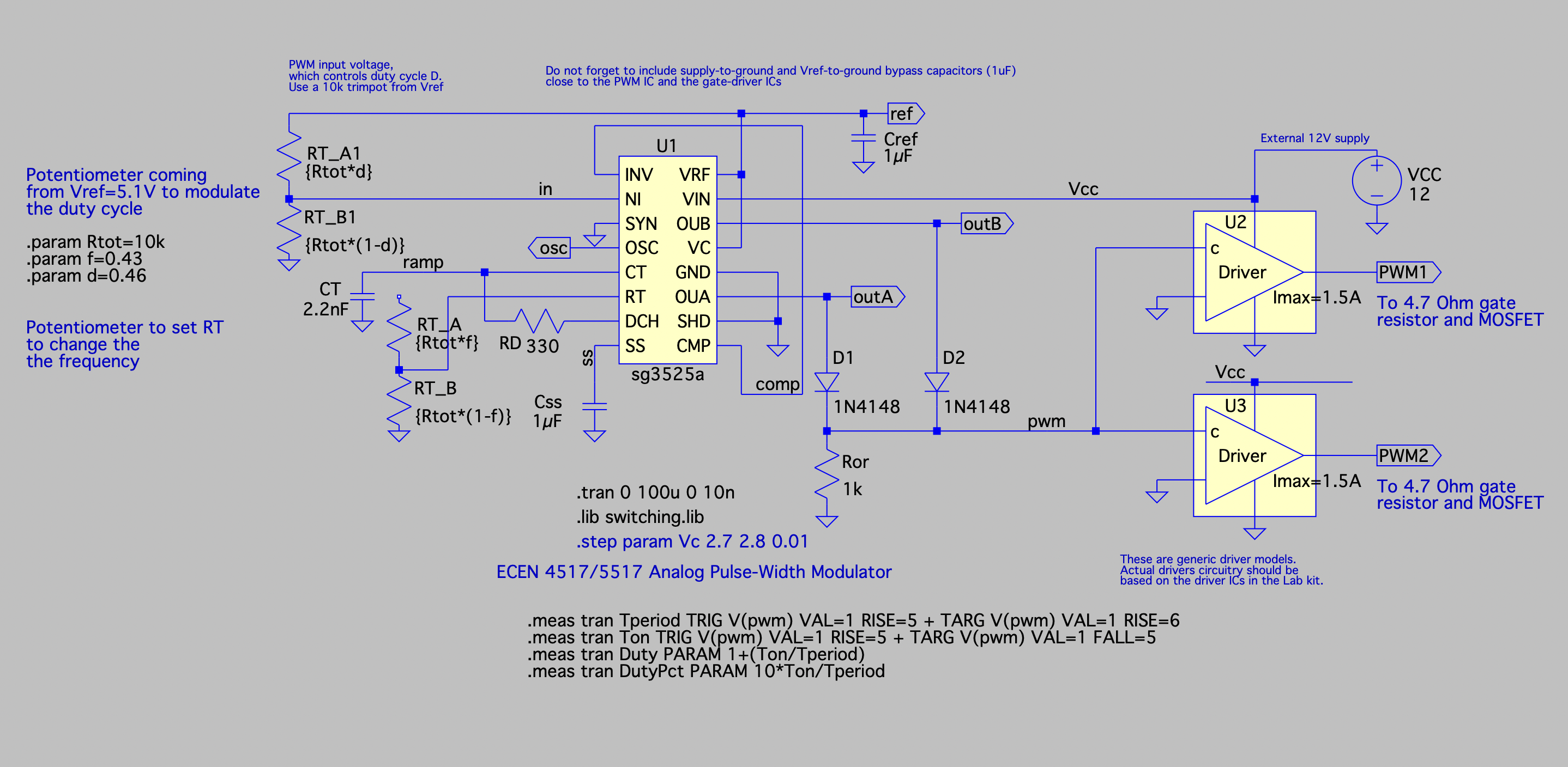
For the cascaded boost converter, an analog PWM circuit consisting of the SG3525 IC was implemented. The IC, which acted as a Pulse Width Modulator Control Circuit, incorporated some peripherals with labeled components and values given in class or selected by good practice.
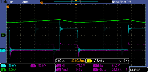
The cascaded boost MOSFET voltages were measured during operation to ensure they didn't exceed the voltage rating of the FETs. Q1 is an IRF540Z with a rating of 100V, while Q2 is FQP11N40C with a rating of 400V. This oscilloscope waveform of Vds1 in purple with a scale of 50 V has maximum value of 64 V. The inductor current of L2 and Vds2 are included in the background.
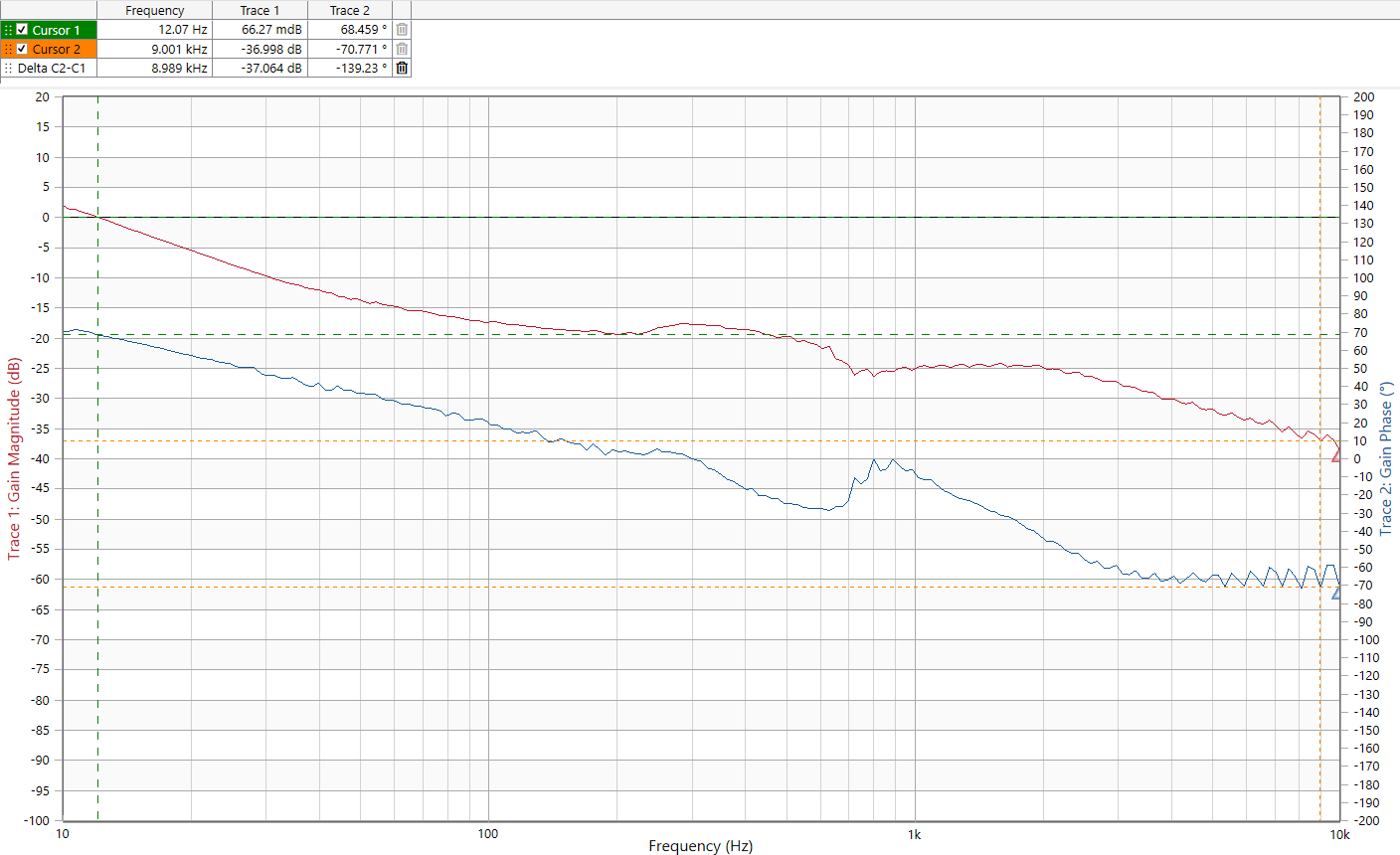
Modified sine wave inverter: Bode 100 loop gain measurement at nominal 150 V where the crossover frequency is measured in cursor 1 as 12 Hz with a phase margin of 68.4°. It is easy to tell that there was a lot of parasitic winding resistance from the two inductors, which heavily damped the response.

Here is the group winning first place in our session at the end-of-the-semester PV Lab expo. The battery was charging with a maximum power from 52-55 W with a 25 W lightbulb load at the output of the inverter. For reference, the solar irradiance was around 1100 W/m^2 and the solar panel has a rated power of 85W.